
Understanding Bug Zapper Circuit Design
Overview of Bug Zapper Functionality – How bug zappers work to eliminate insects using electrical circuits
In the realm of pest control, few innovations have captured the imagination quite like the bug zapper circuit diagram. This elegant yet potent design leverages the fundamental principles of electrical circuits to neutralize pesky insects, transforming a simple concept into a marvel of engineering. At its core, a bug zapper works by attracting insects with ultraviolet light, then delivering a swift, electric shock that eradicates them instantly. The circuit diagram orchestrates this process seamlessly, integrating components like high-voltage transformers, safety switches, and grid electrodes to ensure both efficiency and safety.
Understanding the bug zapper circuit diagram reveals a fascinating interplay of electrical components that collectively create a lethal yet safe environment for humans. When insects are lured into the zapper’s vicinity, they complete an electrical circuit, allowing the high-voltage current to pass through their bodies. This process is a testament to how simple electrical principles can be harnessed for effective pest control, especially in regions like South Africa where insect-borne diseases are a concern. The design intricacies of the bug zapper circuit diagram make it not only a practical device but also a reflection of how technology can harmonize with nature’s nuisances.
Key Components in a Bug Zapper – Essential electronic parts involved in the circuit
Understanding the inner workings of a bug zapper circuit diagram is like peering into a tiny, electrifying symphony of components working in harmony to banish pests. At the heart of this design are essential electronic parts that transform an ordinary device into a pest-eliminating powerhouse. These parts include high-voltage transformers, ultraviolet light bulbs, safety switches, and grid electrodes. Each component plays a vital role—without one, the entire bug zapper circuit diagram could turn into a useless pile of wires and fuses.
For instance, the high-voltage transformer is the beast that ramps up the voltage, preparing the lethal electric grid. Meanwhile, the ultraviolet light bulb acts as the insect magnet, drawing bugs out of hiding. Safety switches are cleverly integrated to prevent accidental shocks, making the device both effective and user-friendly. Sometimes, designers incorporate a
- power supply unit
- fuse connections
to enhance durability and safety. When these components come together within the bug zapper circuit diagram, they create a formidable yet safe pest control solution tailored for South African households battling insects at every turn. Truly, it’s a marvel of engineering with a zap of ingenuity!”
Basic Operation Principles – Electrical principles behind bug zapper effectiveness
At the core of every effective bug zapper circuit diagram lies a fascinating interplay of electrical principles that harness the invisible force of electricity to banish unwelcome insects. The effectiveness of these devices hinges on a delicate balance—where high-voltage power is generated and controlled through precise circuitry, creating a formidable electric grid that zaps pests on contact. This intricate dance relies on the fundamental laws of physics, transforming simple electronic components into a lethal weapon against bugs.
The key to understanding this marvel lies in recognizing how the bug zapper circuit diagram orchestrates the flow of electricity. Once powered, the high-voltage transformer ramps up the voltage, sending it through grid electrodes designed to deliver a swift, lethal shock. The ultraviolet light bulb acts as the bait, drawing insects into the lethal zone, while safety switches ensure the device remains user-friendly and secure. In essence, every element within the bug zapper circuit diagram collaborates seamlessly, turning electrical energy into a pest-eliminating symphony that is both powerful and safe.
Detailed Components of a Bug Zapper Circuit Diagram
High-Voltage Power Supply – Generating the necessary voltage to electrocut insects
At the heart of any formidable bug zapper circuit diagram lies the high-voltage power supply—a marvel of electronic ingenuity that transforms modest electrical input into a lethal, shimmering arc capable of neutralizing unwelcome insects. This power supply is not merely a component but a conduit of electrifying magic, generating the necessary voltage to create an electrified grid that acts as a silent, deadly guardian in the night. Its design revolves around a transformer that steps up the voltage, a pair of rectifiers that ensure a steady flow of current, and a capacitor that stabilizes the output, all working in harmony to produce a potent electrical charge.
In the realm of the bug zapper circuit diagram, understanding this high-voltage section reveals the secret behind its efficiency. The transformer, often a flyback type, is carefully chosen to handle the immense voltage required, while the rectifier diodes prevent backflow, safeguarding the circuit’s integrity. To ensure safety and performance, an additional resistor and a voltage regulator are often incorporated, controlling the flow and preventing accidental shocks. When these components unite in a meticulously crafted circuit diagram, they conjure a formidable electrical fortress that eradicates insects with swift, luminous strikes.
Transformers and Voltage Multiplier Circuits – Converting low voltage to high voltage safely
Within the intricate web of a bug zapper circuit diagram, the transformer and voltage multiplier circuits serve as the enchanted heartbeats of high-voltage generation. These components work in unison to convert humble low-voltage supplies into a formidable electrical force capable of incinerating insects with a single luminous flash. The transformer, often a flyback type, acts as the mighty gateway—stepping up voltage with precision and grace, much like a mythical portal to a realm of electrifying power.
Following this transformation, the voltage multiplier circuits employ a clever arrangement of diodes and capacitors to exponentially elevate the voltage. This process is akin to a magical ascension, where the electrical energy is multiplied safely and effectively. A typical bug zapper circuit diagram features these components harmoniously orchestrated to ensure the high-voltage output is both potent and safe. They form a resilient barrier, sparking the deadly arcs that make bug zappers so formidable.
- The transformer steps down or up the voltage according to the design requirements, often optimized for durability and efficiency.
- The voltage multiplier circuit then takes this stepped-up voltage, multiplying it through a cascade of diodes and capacitors to reach the lethal levels required for insect electrocuting grids.
Understanding these components in the bug zapper circuit diagram reveals the secret behind its formidable efficacy—an elegant dance of electrical transformation and amplification that transforms modest power into a deadly, shimmering shield against pests. Such mastery of high-voltage conversion ensures the bug zapper remains a trusted guardian in South African households, warding off unwelcome guests with luminous, swift justice.
Electrode Grids and Their Role – Design and placement for effective insect extermination
At the heart of every effective bug zapper circuit diagram lies the electrode grid—an unsung hero in insect extermination. These grids are strategically designed to deliver a lethal jolt, transforming innocent bugs into crispy critters with a flash of high-voltage power. Their placement isn’t random; it’s a calculated dance of electrical engineering and pest control finesse. Usually positioned at the top or along the sides of the device, the electrode grids create a shimmering barrier that lures insects in with ultraviolet light before delivering the decisive shock.
Design matters immensely—if the grid is too spaced out, bugs might slip through, but if it’s too dense, it could compromise safety and efficiency. Typically, the electrode grids are constructed from conductive metals like stainless steel wire or fine mesh, ensuring durability in South African outdoor conditions. Proper spacing—often just a few millimeters—is crucial for effective insect contact while maintaining safety standards. This meticulous arrangement guarantees that the electrical arc is both swift and potent, turning an ordinary bug zapper circuit diagram into a pest-eliminating masterpiece.
In essence, the role of the electrode grid is to serve as the final barrier—an electrified fortress where pests meet their doom. When combined with the high-voltage power supply, these grids become the focal point of insect eradication, making bug zappers not just a convenience but a formidable pest control weapon in any South African household or outdoor setting.
Step-by-Step Bug Zapper Circuit Diagram Explanation
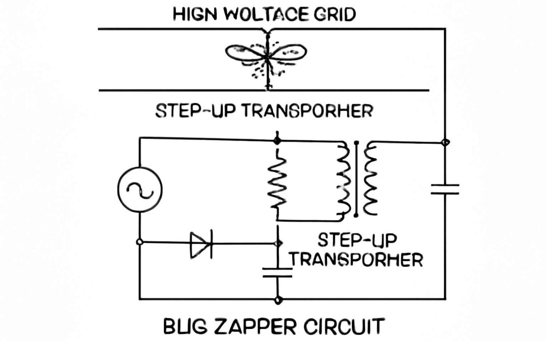
Circuit Schematic Overview – Visual representation and description of circuit connections
Understanding the bug zapper circuit diagram is crucial for building an effective insect killer. The schematic visually maps out how each component connects, ensuring the high-voltage power supply delivers energy safely. At the core, the circuit features a transformer or voltage multiplier circuit, which steps up low voltage to the high voltage needed for the electrode grids. These grids are strategically placed to maximize insect contact and ensure a quick electrocuting process.
The schematic clearly indicates how the power flows from the transformer to the electrodes, with safety switches and resistors integrated to prevent hazards. For clarity, the connections are often represented with simple lines and symbols, making the circuit easier to troubleshoot or modify. When designing or analyzing a bug zapper circuit diagram, pay close attention to the placement of the high-voltage components, as they are vital for the device’s effectiveness in South Africa’s warm climate.
Working Circuit Path – Flow of current from power source to electrodes
In the labyrinth of circuitry that powers a bug zapper, understanding the flow of current is akin to unraveling a mystical river guiding energy from its source to its final, electrifying destination. The bug zapper circuit diagram acts as the enchanted map, revealing the path that transforms humble electrical signals into a lethal storm for unwelcome insects. As the current departs the high-voltage power supply, it journeys through a series of carefully orchestrated components designed to amplify and control its strength.
Within this arcane pathway, a transformer or voltage multiplier circuit takes center stage, escalating the low voltage to a formidable force. From here, the current flows along insulated lines to reach the electrode grids—strategically placed to ensure maximum contact with insects. The schematic diagram guides us through this process, illustrating how the power is routed safely, with key elements such as safety switches and resistors woven into the design to prevent hazards. This seamless flow ensures the bug zapper operates reliably, delivering swift justice to pests lurking in South Africa’s warm, humid evenings.
Safety Features and Interlocks – Protecting users and preventing electrical hazards
Safety features and interlocks within a bug zapper circuit diagram are the silent guardians ensuring user protection while maintaining lethal efficacy against insects. As the electric current surges through the intricate pathways, these mechanisms act as critical checkpoints, preventing accidental contact with high-voltage components. Imagine a well-placed safety switch that instantly disconnects power when the unit is opened or tampered with—this simple yet vital feature is the first line of defense.
To enhance safety, manufacturers often incorporate resistors and fuses into the circuit. These elements serve as safeguards, limiting current flow and preventing overloads that could lead to electrical hazards. Moreover, interlock switches are strategically positioned—often near access panels—to ensure the high-voltage grid is deactivated before any internal inspection or cleaning occurs.
In the context of a bug zapper circuit diagram, these safety features are seamlessly integrated, creating a resilient barrier against potential mishaps. They contribute not only to user safety but also to the longevity and reliable operation of the device. As we explore the schematic, you’ll notice how each component plays a pivotal role in weaving a protective net around the lethal core—making sure that the zapper functions effectively while safeguarding those around it.
Design Considerations for an Effective Bug Zapper Circuit
Voltage and Current Specifications – Optimal electrical parameters for safety and efficiency
In the shadowed realm of insect elimination, the precision of electrical parameters can mean the difference between an effective trap and a flickering failure. When designing a bug zapper circuit diagram, the voltage and current specifications must be approached with a blend of artistry and caution. Too high, and safety risks escalate; too low, and the insects remain unscathed, lingering in darkness. Achieving that delicate balance ensures the zapper operates with optimal efficiency, drawing power that is potent yet controlled.
To craft a truly formidable bug zapper circuit diagram, one must pay close attention to the voltage multiplier circuits and transformer configurations, which elevate the low voltage to deadly heights—often reaching 10,000 volts or more. The current, however, should remain within safe limits, generally in the microampere range, to prevent electrical hazards while delivering a lethal jolt to unwelcome guests. This fine-tuning is vital not only for safety but also for the longevity of the device.
In essence, the key lies in selecting electrical components that harmonize power and protection. An effective bug zapper circuit diagram balances these elements, ensuring each zap is a swift, silent strike—leaving no room for error or mishap. The proper electrical parameters forge a marriage of efficacy and safety, transforming a mere schematic into a beacon of darkly charming pest control mastery.
Material Selection for Electrodes – Choosing durable and conductive materials
In the shadowy dance of insect eradication, the heart of every successful bug zapper circuit diagram lies in the choice of materials for the electrodes. Selecting materials that are both highly conductive and resistant to corrosion is essential to ensure durability and consistent performance. Copper and stainless steel often lead the charge—they offer excellent conductivity and longevity, standing firm against the relentless assault of airborne pests. These materials must be carefully integrated into the circuit to maintain electrical integrity over time, especially in humid South African climates where moisture can accelerate wear.
To amplify the effectiveness of the bug zapper circuit diagram, consider the electrode design and placement. A well-crafted grid with precise spacing maximizes insect contact, while robust material choices ensure each zap packs a punch. When designing, keep in mind that electrode materials should also be safe for users; thus, insulation and protective coatings are vital to prevent accidental shocks. A thoughtful selection of electrode materials not only enhances pest control but also extends the lifespan of the device, making it a reliable companion in the fight against insects.
Power Supply Options – AC vs DC power sources and their implications
Power supply choice is pivotal in the design of an effective bug zapper circuit diagram. In South Africa’s humid climate, the decision between AC and DC power sources impacts both safety and performance. AC power, readily available from mains outlets, simplifies wiring but demands rigorous safety features to prevent electrical hazards. Conversely, DC power offers more flexibility, especially for portable or solar-powered bug zappers. This route often involves a transformer or voltage multiplier circuits to generate the high voltage necessary for insect electrocuting grids.
When selecting the right power option, consider the device’s intended use. For stationary outdoor units, AC might be more practical; for portable units, DC is preferable. An integrated bug zapper circuit diagram should clearly illustrate the power flow, highlighting key components like transformers and voltage regulators. Ultimately, the goal is a safe, reliable device that maintains high voltage output without risking user safety or device longevity.
Understanding these nuances ensures the circuit can deliver consistent pest control while adapting to local conditions. Whether it’s a rugged mains-powered design or a versatile battery-operated model, the power supply forms the backbone of an efficient bug zapper circuit diagram.
Building and Testing a Bug Zapper Circuit
Tools and Components Needed – List of necessary hardware and electronic parts
Crafting a bug zapper circuit diagram is akin to weaving a tapestry of electrical artistry—each component plays a vital role in orchestrating a symphony of insect eradication. To breathe life into your project, a precise selection of hardware and electronic parts is essential. These include high-voltage transformers, voltage multipliers, and resilient electrode grids designed to withstand the relentless assault of buzzing pests.
Building this circuit requires more than just assembly; it’s an exercise in harmony and safety. A reliable power supply—whether AC or DC—serves as the heartbeat, energizing the entire system. The correct material choice for the electrodes ensures durability and conductivity, vital for maintaining peak performance in South Africa’s diverse climate. Remember, the key to a successful bug zapper circuit diagram lies in balancing power, safety, and ingenuity—transforming ordinary components into a formidable insect assassin!
Assembly Tips and Precautions – Best practices to ensure proper construction and safety
Constructing a bug zapper circuit diagram is an intricate dance between innovation and caution. As you assemble your project, attention to detail ensures both effectiveness and safety. A steady hand and meticulous wiring prevent unintended electrical faults that could pose hazards. When connecting components, double-check the polarity of high-voltage transformers and voltage multipliers—mistakes here can be costly. The resilient electrode grid must be securely mounted, maintaining proper spacing to avoid accidental shocks while maximizing insect contact. Remember, safety features such as interlocks and insulation barriers are paramount—they serve as your silent guardians against electrical mishaps.
During testing, start with low voltage levels to observe the circuit’s behavior before ramping up to operational voltage. Ensure your power supply is stable and correctly rated, as fluctuations can diminish performance or compromise safety. It’s wise to incorporate a fuse or circuit breaker—these simple yet crucial safeguards protect both the circuit and the user. When working with a bug zapper circuit diagram, patience and precision are your allies. Each connection should be firm, each component tested thoroughly, and safety protocols never overlooked. Only then can you achieve a harmonious blend of power, safety, and insect eradication mastery.
Testing Procedures – Methods to verify functionality and safety of the circuit
Embarking on the journey of building a bug zapper circuit diagram is akin to orchestrating a delicate symphony of electrical precision and safety. The thrill lies in witnessing your creation come alive, zapping insects with efficient finesse. Yet, before you dive into the electrifying world of high-voltage circuits, a judicious testing procedure is paramount. It’s not merely about flipping a switch and hoping for the best; it’s about verifying that every component functions harmoniously and safely. A meticulous approach to testing ensures your bug zapper circuit diagram performs optimally without risking unintended shocks or circuit failures.
Begin with a cautious power-up at low voltage levels—think of it as a gentle handshake before the full embrace. Observe the circuit’s behavior, ensuring the electrode grid is correctly mounted and insulated. Next, check the voltage output with a multimeter, confirming it aligns with your design specifications. If everything appears stable, gradually increase to the operational voltage while keeping a keen eye on safety features such as interlocks and insulation barriers. Remember, incorporating a fuse or circuit breaker is your best safeguard against unexpected electrical mishaps. With patience and methodical testing, you’ll guarantee that your bug zapper circuit diagram is both effective and safe—ready to keep those pesky insects at bay while respecting every nuance of electrical safety protocols.
- Verify the voltage output matches the circuit diagram specifications.
- Ensure the electrode grid is securely mounted and properly insulated.
- Test safety features such as interlocks and circuit breakers before full operation.
Troubleshooting Common Issues in Bug Zapper Circuits
No High Voltage Output – Diagnosing transformer and multiplier circuit problems
When a bug zapper circuit diagram fails to produce high voltage output, it often signals underlying issues within the transformer or voltage multiplier circuit. These components are crucial for elevating low-voltage power into the lethal jolt that exterminates insects effectively. Diagnosing these problems requires a keen eye and a methodical approach, as subtle faults can have a significant impact on circuit performance.
Common issues include burned-out transformers, faulty diodes, or loose connections within the multiplier circuit. To pinpoint the source, start by inspecting the transformer for any visible signs of damage or overheating. Next, test each diode within the voltage multiplier with a multimeter set to diode mode; a failed diode can halt the entire high-voltage generation process. Additionally, verify the integrity of the wiring and solder joints—sometimes, a simple loose connection or cold solder joint can prevent the circuit from functioning correctly.
- Check transformer output voltage with a multimeter to ensure it’s within specifications.
- Test the diodes in the voltage multiplier circuit for continuity and forward voltage drop.
- Inspect all connections for corrosion or damage, especially around high-voltage components.
By systematically troubleshooting these elements, you can restore the bug zapper circuit diagram to optimal operation, ensuring it delivers the necessary high-voltage strike to eliminate pests effectively.
Inconsistent Insect Zapping – Identifying conductivity and electrode issues
Inconsistent insect zapping can be a frustrating mystery, especially when your bug zapper circuit diagram seems flawless. Often, the culprit lies in conductivity issues within the electrode grid or faults in the circuit wiring. A slight misalignment or corrosion can dramatically reduce the electrical current passing through the electrodes, rendering your device ineffective.
To diagnose these problems, start by inspecting the electrode materials and connections. Use a multimeter to test conductivity across the grid—any break or high resistance indicates a potential fault. Sometimes, the problem is as simple as a loose solder joint or a broken wire. Remember, the high-voltage section of your bug zapper circuit diagram demands impeccable connections to function optimally. Ensuring the electrodes are properly grounded and free of debris can make all the difference in delivering that lethal jolt that exterminates pests.
By paying close attention to these conductivity and electrode issues, you can restore your bug zapper’s zapping power. When the electrical pathway is intact and efficient, insects won’t stand a chance against the lethal circuit—making your bug zapper circuit diagram a true pest extermination marvel.
Safety Concerns – Ensuring proper insulation and circuit protection
Electrical gremlins lurking in your bug zapper circuit diagram can turn a pest control hero into a frustrating zero. Safety concerns are paramount, especially when working with high-voltage circuits that could give even seasoned electricians a run for their money. Proper insulation and circuit protection aren’t just recommended—they’re essential. Think of it as giving your bug zapper a sturdy armor shield, preventing accidental shocks and electrical fires from turning your pest extermination plan into a disaster show.
One sneaky trap is overlooked grounding. Without a solid ground connection, high-voltage potentials can stray onto unintended surfaces, creating a hazardous environment. To avoid this, double-check all wiring connections and ensure the circuit is protected with appropriate fuses or circuit breakers. Incorporating safety features and interlocks in your bug zapper circuit diagram guarantees that the lethal volts stay where they belong—on those pesky insects, not on your unsuspecting fingers.
- Verify insulation around all high-voltage components.
- Ensure circuit enclosures are sealed and resistant to dust and moisture.
- Use rated components that can handle the electrical stress without breaking a sweat.
By weaving these safety elements into your bug zapper circuit diagram, you create a pest extermination device that’s both effective and secure. After all, nothing kills the vibe faster than a shocking accident—literally or figuratively. So, keep safety at the forefront, and your bug zapper will happily zap pests without zapping itself in the process!
Enhancing Your Bug Zapper Circuit Design
Energy Efficiency Tips – Reducing power consumption while maintaining performance
Improving energy efficiency in a bug zapper circuit diagram isn’t just about saving power; it’s about making the device smarter and more sustainable. By optimizing circuit components and reducing unnecessary electrical load, you can maintain high insect elimination performance without draining your power source. For instance, using energy-efficient transformers and voltage multiplier circuits ensures that the high-voltage output remains effective while consuming less energy.
It’s also vital to select materials for electrodes that offer excellent conductivity with minimal resistance, which reduces power wastage. Incorporating smart control features, such as automatic shutdowns or timers, can further enhance efficiency by preventing continuous operation when not needed.
Remember, a well-designed bug zapper circuit diagram balances power consumption with performance—delivering reliable insect control while keeping energy bills in check. In the broader context, these improvements contribute to more environmentally conscious pest management solutions.
Adding Features – Incorporating UV light or timer functions
Enhancing your bug zapper circuit diagram with innovative features can transform a simple insect eliminator into a marvel of modern pest control. Imagine integrating UV light technology or timer functions—these additions not only heighten efficiency but also make the device more user-friendly. UV light acts as a beacon for insects, drawing them irresistibly toward the electric grid, while timer features allow precise control over operation hours, conserving energy and prolonging device lifespan.
Incorporating a UV light into your bug zapper circuit diagram elevates its performance by attracting more insects, especially during twilight hours. Meanwhile, a timer ensures that the zapper is active only when needed, reducing unnecessary power consumption and increasing sustainability. For a seamless upgrade, consider using a relay switch controlled by an adjustable timer module, which can be integrated without disrupting the core circuit.
By thoughtfully adding these features, you craft not just a pest control device but a harmonious blend of technology and nature’s rhythm—an irresistible dance of light and electricity that keeps pests at bay while respecting the environment. These enhancements demonstrate how a well-designed bug zapper circuit diagram can be both a practical and an elegant solution for modern pest management in South Africa’s diverse climate and insect landscape. Embrace the potential of your circuit, and watch your bug zapper evolve into a beacon of both efficiency and ingenuity!
Design Improvements for Safety and Durability – Upgrading circuit components
Enhancing your bug zapper circuit diagram for safety and durability transforms a basic insect killer into a resilient, long-lasting device. Upgrading circuit components—such as selecting high-quality resistors, insulated wiring, and robust enclosures—ensures the circuit can withstand South Africa’s diverse climate conditions. These improvements not only boost performance but also protect users from electrical hazards, especially considering the high-voltage elements involved.
A critical focus should be on circuit safety features. Incorporating protective devices like fuses or circuit breakers can prevent overloads, while proper insulation minimizes the risk of accidental shocks. For added durability, using weather-resistant materials ensures the bug zapper circuit diagram remains reliable during the rainy season or in dusty environments.
To streamline maintenance, consider integrating a diagnostic LED indicator that signals circuit faults. This small addition can save time and enhance safety during troubleshooting, ultimately extending the lifespan of your bug zapper.