
The Inner Workings of High-Voltage Pest Elimination Devices
Understanding the Basic Electrical Principle
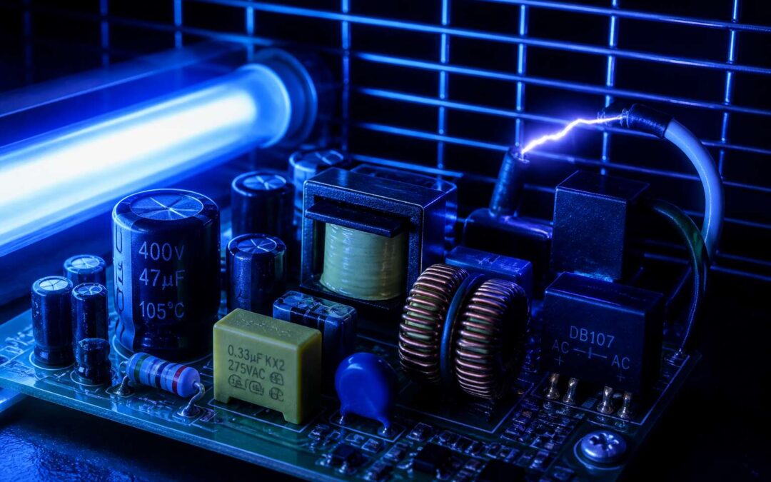
Most South Africans assume a bug zapper circuit board is a simple contraption, but it is a miniature high-voltage generator. The core principle hinges on a voltage multiplier network, typically a Cockcroft Walton generator, which steps up the 220V wall supply to a lethal 2,000V or more. This high voltage sits across a metal grid, waiting to fry any insect that bridges the gap.
This circuit board houses specific components that work in a rhythmic cascade:
- Capacitors that store a charge.
- Diodes that force current in one direction.
- A resistor that limits the initial surge.
When a mozzie lands, it creates a short circuit, discharging the capacitors in a microsecond burst. Instead of a steady stream, it delivers a rapid pulse. The result is a satisfying zap and a fried exoskeleton, all managed by a board that costs less than a loaf of bread. Understanding this electrical principle helps you pick a unit that won’t trip your trip switch during a summer storm.
Role of Step-Up Transformers in Voltage Amplification
But before any voltage multiplication can occur, the bug zapper circuit board must overcome a different constraint. The 220V wall supply needs amplification before the Cockcroft Walton stage even sees it. Here, the step-up transformer earns its place. It takes the mains voltage and elevates it to a preliminary level, often several hundred volts, which the subsequent multiplier stages then stack further.
Without this initial elevation, the final discharge lacks the energy to kill anything larger than a fly. The transformer operates at a frequency far higher than the mains supply. This is not a design quirk. It allows for a smaller, cheaper magnetic core. A unit running at 20kHz can use a transformer that fits in the palm of your hand. The cost saving is significant. A functional device sells for under R200 in most South African hardware stores.
Capacitors and Their Charging Mechanisms
The capacitors on a bug zapper circuit board store lethal potential. They accumulate energy in silence, then release it in a crack. The build is silent; the release is a calculated pulse. The charging mechanism relies on high-frequency output from the transformer, rectified into a pulsating DC current. Each cycle pushes packet of electrons into bank.
The rate of these packets dictates voltage ceiling. A larger capacitance holds more charge, but lengthens the time to reach breakdown threshold of air. The diode arrangement ensures one-way flow, preventing stored energy from leaking back.
These govern the charging speed:
- Capacitance value in microfarads.
- Peak voltage of the rectified supply.
- Internal resistance of the diode stack on the bug zapper circuit board.
A lower resistance allows faster accumulation, but it stresses the components. In a South African summer, where flying pests are relentless, this mechanism works without pause, hundreds of times per second!
The Grid Discharge Process Explained
When a winged pest bridges the gap between the grid electrodes, the air in that sliver of space loses its insulating properties. The impedance drops, and the bug zapper circuit board responds by dumping the capacitor bank’s stored energy through the insect’s exoskeleton. The current climbs from negligible to hundreds of amperes in nanoseconds.
The breakdown follows a precise sequence:
- Ionization of air creates a conductive plasma channel.
- The capacitor bank discharges a high-frequency, high-current pulse.
- The energy dissipates as heat, disrupting the insect’s nervous system.
- The gap deionizes and returns to standby.
The entire event takes under a millisecond. The discharge current is limited only by the internal impedance of the bug zapper circuit board and the resistance of the insect. In humid South African evenings, moisture on the grid can trigger false discharges, draining the bank without delivering an effective strike.
Key Electronic Components and Their Functions
Semiconductor Diodes in Voltage Multiplier Circuits
The semiconductor diodes in the voltage multiplier circuit conduct current in only one direction. They rectify the high-frequency alternating current from the transformer, turning it into a pulsed direct current that accumulates charge across the capacitors. Without them, the circuit cannot build the electrostatic tension required for a fatal strike.
I have seen many bug zapper circuit board failures traced back to these specific components! They must endure conditions that would overwhelm lesser parts. Consider the essential traits of a robust diode:
- High peak inverse voltage to resist reverse breakdown.
- Fast reverse recovery time to keep up with the grid’s pulse.
- Steady forward current capacity to avoid thermal runaway.
When a diode fails, it typically short-circuits or opens up, starving the multiplier of its needed rectification. The result is a grid without charge, even as the transformer continues to hum.
Resistors and Current Regulation
Resistors on a bug zapper circuit board handle the essential task of current regulation. They limit the amount of current flowing into sensitive sections, preventing the transformer from overworking itself. A resistor that drifts out of tolerance causes erratic charging behavior, leaving the grid below the strike threshold. I have seen charred resistors in units that still hummed but produced nothing. The resistance value matters, and so does the wattage rating. A resistor rated too low for the duty will overheat and fail over time.
A common arrangement includes:
- A current-limiting resistor near the transformer output to cap the initial surge.
- Bleeder resistors across capacitor banks to drain residual voltage between pulses.
These parts operate quietly, but when they fail, the entire circuit behaves differently.
Power Supply Rectification and Filtering
Power supply rectification and filtering turn raw mains alternating current into the steady voltage a bug zapper circuit board demands. Most units use a full wave bridge rectifier, a stack of four diodes that flips each negative half cycle. The result is pulsating DC, which still contains ripple. If that ripple reaches the pulse generation stage, timing shifts and strike voltage drops. In South Africa, where load shedding makes mains frequency unstable, this section becomes critical.
I have seen boards where a single failed rectifier diode turned the output into a half wave mess. The unit hums, but the ionization on the grid becomes weak. Filtering then relies on electrolytic capacitors and sometimes a choke to smooth the residual AC. A bug zapper circuit board without proper filtering produces uneven high voltage pulses. Trust me, that is a real problem.
Here is what usually sits in the rectification and filtering section:
- Bridge rectifier rated at twice the incoming current
- Smoothing capacitor with adequate ripple current rating
- A series choke for high frequency noise suppression
Protective Fuses and Surge Suppression
Consider a thunderstorm over Johannesburg. The grid stutters, then a surge races toward your backyard. Without intervention, that spike would carve through the bug zapper circuit board in microseconds. Protective fuses act as sacrificial sentinels, melting to break the circuit. Surge suppression, however, works differently. It diverts excess energy to the ground before it reaches sensitive components. Most boards use a metal oxide varistor, which clamps voltage spikes with astonishing speed. I have seen boards where a missing suppressor caused catastrophic failure after one lightning event.
Some units add a thermal fuse for slow overheating. Others rely on resettable breakers. The result is resilience, not just protection. You might find these elements:
- A fast acting glass fuse for short circuit events
- A metal oxide varistor rated for repeated surges
- A grounding path with low resistance
Each part earns its place by sacrificing itself or shunting harm away. That is why a bug zapper circuit board remains functional through South Africa’s volatile electrical weather.
Electrode Materials and Grid Construction
Every bug zapper circuit board is a silent executioner, but its blade is the electrode grid. This mesh of charged metal does the final, fatal work. Most grids are built from stainless steel or galvanised iron, chosen for their resistance to the corrosive cocktail of insect remains and nightly dew. Copper conducts brilliantly, yet it tarnishes too quickly in the Highveld air, so manufacturers often pass on it.
The spacing between these electrodes is a matter of electrical physics. If they sit too far apart, the voltage fails to arc across the gap. Too close, and a mere dust mote triggers a discharge. A well tuned grid holds a gap of roughly 2 to 4 millimetres, forcing the flying insect to physically bridge the distance and complete the circuit. The grid’s supporting frame also carries a charge, which adds to the effective kill zone.
Construction quality dictates longevity. A flimsy grid that flexes in the wind will eventually short against its own support brackets. The best designs use rigid, thick gauge wire that holds its alignment through seasons of storms and scorching sun. When you inspect a bug zapper circuit board, remember that its high voltage output is only as good as the metal that receives it. The components behind the grid, including the transformer and multiplier, work in concert with this physical barrier. A robust grid is the final proof of a durable unit. It is the difference between a device that lasts a decade and one that fails after a single wet season.
For a grid to perform optimally, it requires:
- Corrosion resistant electrode material such as 304 grade stainless steel
- Precise spacing maintained by non conductive mounting clips
- Strong frame tension to prevent sagging and warping
The surface finish of the electrodes matters more than most realise. A rough, pitted surface collects debris and reduces the efficiency of each discharge. A polished, smooth rod allows insects to be vaporised cleanly, and the residue falls away instead of clinging to the metal. This self cleaning action is crucial in a country where mosquitoes swarm in humid summers. The grid, therefore, is not just a passive fence. It is an active participant in the daily cycle of attraction, discharge, and disposal. The entire bug zapper circuit board depends on this final stage to deliver its intended service. Without a properly constructed grid, even the most advanced electronic heart is rendered useless.
Troubleshooting Common Electrical Failures
Identifying Non-Functional High-Voltage Output
When the high-voltage output fails, the entire bug zapper circuit board becomes a silent instrument. I start by measuring the voltage across the transformer secondary winding, using a multimeter set to the highest range. A reading near zero often points to an open primary winding or a broken solder joint on the input side.
Next, inspect the diode multiplier stack. Any single failed diode can halt the voltage cascade, leaving the grid lifeless. Look for visible burning or measure each diode in forward and reverse bias. Also verify the capacitor bank; leaky capacitors will absorb charge without delivering the expected discharge.
- Check the mains input fuse and ensure no short circuit.
- Examine the high-voltage output points for carbon tracking.
Careful observation reveals the culprit, restoring the circuit board to its intended purpose.
Testing the Voltage Multiplier Stages
The silence of a dead grid is a peculiar kind of loud. When the transformer output reads correctly, yet the zap fails, the fault lies deeper within the bug zapper circuit board. We move past the primary windings and into the delicate dance of the voltage multiplier stack, where each diode and capacitor performs a precise step.
Testing this section requires a methodical approach. A single diode that has failed open will stop the entire cascade, preventing the voltage from climbing to its lethal peak. The capacitors, too, can betray the system; a leaky unit will dissipate the stored energy as heat instead of holding it for the next pulse. Measuring the voltage at each stage of the multiplier reveals the exact point where the amplification ceases. To do this efficiently:
- Power down the unit and discharge the capacitor bank with an insulated tool.
- Set your multimeter to measure DC voltage and attach the probes to the output of the first multiplier stage.
- Power up briefly and note the reading. It should be roughly double the transformer’s secondary output.
- Move the probes to the next stage and repeat the process, watching for a voltage drop that indicates a failed component.
This sequential check acts as a map, isolating the faulty semiconductor. A capacitor with a shorted dielectric will show a normal voltage reading at rest but will fail to hold a charge under load. The subtlety here is that a bug zapper circuit board can appear healthy during static tests, only to fail when the circuit is under strain. Look for bulging capacitor tops or a faint discoloration around the diode bodies, which are signs of thermal distress. These symptoms often point to a component that gives up only when the system demands its full potential.
Replacing Burnt or Corroded Components
Corrosion works quietly. In coastal regions, salt-laden air creeps into every joint and lead on the bug zapper circuit board, turning a healthy connection into a brittle, green-tinged failure. A burnt resistor, by contrast, usually points to overcurrent or a shorted component downstream. Replacing it without addressing the cause is a temporary fix.
The replacement process demands care. Desolder the damaged part, then inspect the pads for lifted traces or carbon scoring. Clean the area with isopropyl alcohol before installing the new component. Pay attention to the orientation of polarised parts. A poorly seated replacement will fail just as quickly as the original.
Common failure points include:
– Diode leads corroded at the solder joint
– Capacitor legs snapped from thermal cycling
– Resistor bodies charred from sustained overload
A full voltage test after each replacement on the bug zapper circuit board confirms the repair holds under load.
Maintenance, Safety, and Compliance
Safe Discharge Procedures Before Servicing
Electricity stored in a bug zapper circuit board can hold a lethal charge even after the unit is unplugged. Technicians in South Africa often overlook this latent energy, and that oversight has caused avoidable injuries. Proper maintenance begins here, with respect for what remains unseen.
Before any servicing, follow a strict discharge protocol:
- Disconnect the unit from power and wait ten minutes.
- Bridge the grid terminals to ground using an insulated screwdriver.
- Verify with a voltmeter that residual potential reads zero.
These steps are compliance requirements under occupational safety guidelines, not optional formalities. A clean circuit board resists tracking and corrosion. Wipe dust with a dry brush and inspect solder joints for hairline cracks. Safety is a ritual; every service session starts with discharge and ends with verification.
Cleaning and Preventing Corrosion on Metal Contacts
Corrosion on a bug zapper circuit board is not a cosmetic issue. It is a conductivity killer. Metal contacts in the grid and multiplier stages suffer from moisture, salt air, and insect residue. In coastal provinces like KwaZulu-Natal or the Western Cape, buildup accelerates. Inland, Highveld thunderstorms bring humidity that degrades contacts faster than owners expect.
A routine cleaning plan changes this. Use isopropyl alcohol and a soft brush to lift oxidation from solder pads and terminal points. Do not scrape with metal tools. That removes protective plating and creates future failure sites. Reapply dielectric grease to connector pins after cleaning. It blocks moisture and slows galvanic reaction between dissimilar metals.
For regular servicing:
– Inspect contacts every three months in coastal zones
– Check for green or white residue on copper traces
– Replace terminals with pitting beyond surface level
A clean bug zapper circuit board keeps voltage delivery stable and reduces arcing and premature component failure.
Weatherproofing Considerations for Outdoor Installation
In my experience, outdoor bug zapper circuit board failures often begin with weather, not electricity. South African summers bring UV exposure, driving rain, and hail. A circuit board that survives winter in Gauteng may not last a coastal season in Durban.
Proper weatherproofing needs three things: a sealed enclosure with a high IP rating, pliable gaskets, and cable entries that prevent water running along wires. Drainage holes prevent condensation pooling inside. Sealing is not enough; ventilation must balance against moisture ingress.
- Check gaskets every six months for cracks or hardening
- Confirm cable entry fittings are tight and facing downward
- Replace cloudy or warped translucent covers
Compliance with SANS requirements for outdoor electrical equipment is not optional. A properly rated enclosure protects the bug zapper circuit board and also protects the people who service it. When weatherproofing fails, current can leak to exposed metal surfaces, creating a hazard.
Meeting Electrical Safety Standards and Certifications
The most dangerous 100 grams in a South African backyard is the circuit board of an insect zapper. Maintenance is a cycle, not a fix. Check every connection, every capacitor, and every track for micro cracks. A single compromised trace can turn a harmless device into a live wire.
Safety demands proper isolation before any service. Compliance requires the circuit board to meet the relevant SANS standards and carry certification from a recognised body. Without it, your insurance is void and your liability is real.
- Inspect the certification mark each season
- Perform insulation resistance tests at rated voltage
- Document every repair for audit trails
Routine testing shows hidden wear. That is how the bug zapper circuit board stays lawful, and more importantly, alive.
Proper Disposal of Faulty Electronic Parts
A dead bug zapper circuit board still holds charge. The capacitors can bite you even after removal. That is why maintenance means handling every faulty part with the same caution as a live one.
Keep a dedicated container for replaced components. Do not toss them into the general waste bin. Heavy metals and residual voltage do not disappear at the landfill.
Here is the routine I follow:
- Discharge each removed capacitor with a resistor.
- Wrap corroded electrodes in tape before transport.
- Deliver the lot to a certified e-waste recycler.
Safety and compliance end with disposal. A certified recycler documents the chain, which protects your liability. The bug zapper circuit board may be faulty, but the responsibility is not. Proper disposal closes the maintenance loop.
Minimizing Risk to Pets and Children
An unguarded bug zapper circuit board poses a real risk for pets and children. The voltage may be low current, but a toddler’s wet fingers or a puppy’s chewing habit turn that risk into injury. I treat every unit as live, even after disconnection, and I verify the housing integrity before each season.
Compliance with local electrical codes forms the baseline. Yet compliance alone misses the gaps where curiosity wins. Secure mounting and routine checks matter more than any certificate.
- Position the unit beyond climbing reach.
- Seal every entry point for insects and small paws.
- Replace cracked casings immediately.
This habit protects the whole household. The unit stays functional while your children play and your pets roam without supervision.
Performance Optimization Strategies
Adjusting Grid Spacing for Different Insect Sizes
The grid itself is a silent snob, and it judges its dinner guests by wingspan. A bug zapper circuit board outputs a fixed voltage, but the physical spacing of the electrodes determines which insects actually complete the circuit. Too wide a gap, and smaller gnats fly through unscathed, laughing at your wasted electricity. Too narrow, and larger moths might bridge the gap but fail to receive a lethal jolt, resulting in a confused, slightly singed survivor.
To achieve optimal performance, you must match the electrode distance to the local pest profile. The science is simple: the air gap is part of the circuit, and its breakdown voltage is directly proportional to distance. Adjusting this spacing changes the effective impedance that the high voltage must overcome.
Consider the target demographics for your average South African garden:
– Mosquitoes and midges require a tight gap of roughly 1.5 to 2 mm to ensure they trigger the discharge.
– House flies need a moderate spacing of 2.5 to 3.5 mm for reliable contact.
– Larger moths and beetles demand a wider gap of 4 to 5 mm to prevent immediate arcing without physical contact.
If you are building a unit for a specific location, you might sacrifice the broad spectrum approach for a dedicated assassin. A fixed configuration on the bug zapper circuit board cannot adapt on the fly, so you must choose your battlefield wisely. A grid tuned for mosquitoes will simply bounce off a fat bluebottle, while a wide grid designed for moths will ignore the tiny biting pests entirely. The trade-off is absolute, and the insects will not negotiate.
Integrating UV Lure Lamps Effectively
A UV lamp does more than illuminate the kill zone. It selects the audience. Mosquitoes and midges respond to wavelengths around 365 nm, while certain moths prefer 395 nm. A fixed lamp output limits your reach, so choose the tube that matches your local pest profile.
Placement matters more than most builders realize. The lamp should sit parallel to the grid, roughly 20 to 30 mm away. This distance ensures insects fly toward the light and encounter the electrodes before they can circle away.
Consider these positioning rules:
– Mount the lamp vertically to match the grid’s orientation.
– Keep reflective backing behind the lamp to amplify its output.
– Position the lamp so the grid blocks the direct glow, forcing insects to pass through the electrodes.
The bug zapper circuit board then does its job, delivering the stored charge the moment an insect bridges the gap. A lamp that pulses or flickers can reduce the board’s effectiveness, so maintain steady current. Without a properly integrated lamp, even a bug zapper circuit board produces nothing but a silent, dark box.
Reducing Energy Consumption Without Losing Efficacy
A bug zapper circuit board that runs at full capacity all night wastes energy when no insects are present. The grid holds charge for thousands of milliseconds, and every discharge forces the board to recharge. A photocell or timer shuts the board down during daylight hours, cutting usage by a quarter or more.
- Reduce the capacitor bank’s idle voltage by 10 percent. Insect kills stay consistent because the discharge threshold only needs to exceed the breakdown voltage of a mosquito.
- Pulse the charging cycle instead of continuous operation. A 20 percent duty cycle still delivers a lethal jolt when an insect bridges the gap.
- Use a grid sensor that detects capacitance changes. The board charges on demand, not constantly.
Each strategy requires reworking the bug zapper circuit board’s control logic, but the efficacy loss is negligible. The lamp remains the main draw. Maintain steady current to the UV tube, and keep the kill zone bright. You save power, not results.
Upgrading Components for Extended Lifespan
Performance optimization is a matter of component endurance. A bug zapper circuit board that survives years of coastal humidity and highveld thunderstorms requires deliberate upgrades, not reactive repairs. I have seen stock capacitors fail within one season. Replacing them with metallised polypropylene film capacitors rated for 105 degrees Celsius changes the board’s character entirely.
Address these upgrades in order of impact:
- Replace the diode stack with higher voltage rated rectifiers that tolerate transient spikes.
- Use a conformal coating on the bug zapper circuit board to shield tracking paths from moisture.
- Install a slow blow fuse that matches the inrush current without nuisance trips.
Each choice reduces thermal stress and corona discharge, the two primary causes of high voltage assembly failure. The lamp ballast also deserves attention; a steady current protects the tube and the board’s feedback loop. Extended lifespan emerges from fixing failure points before they cause downtime.
Environmental Impact and Ethical Considerations
Effect on Beneficial Pollinators
In my years of installing these devices across the Karoo, I have seen how a bug zapper circuit board can become a double edged sword. The ultraviolet light attracts not only mosquitoes but also moths, bees, and other beneficial pollinators. This collateral damage is often overlooked.
Consider the following:
- The local honeybee population faces pressure
- Pollination of indigenous flora drops noticeably
- Nocturnal pollinators like hawk moths suffer most
I once watched a farm struggle with poor fruit set. The culprit was an overzealous zapper. A properly tuned bug zapper circuit board should target biting insects only. Timing the operation and positioning the unit away from flowering plants makes a difference.
Responsible Placement to Maximize Target Pest Capture
The placement of a bug zapper circuit board matters as much as the voltage across its grid. I have seen units mounted beside verandas where families gather, the blue glow drawing swarms away from the braai but also into the path of children. The ethical question is not whether to kill pests, but how selectively we do it.
Consider the acoustic footprint. A high-pitched hum from a bug zapper circuit board can disturb sleep and drive neighbours to complain. More importantly, the position determines what dies. Place the unit near stagnant water, not near the vegetable patch.
- Mount the zapper at least fifteen metres from outdoor dining areas.
- Aim the light toward open veld, never toward flowering shrubs.
- Set the timer to run only during peak mosquito hours, usually dusk.
This approach reduces collateral harm while keeping the grid effective. The bug zapper circuit board becomes a tool, not a trap for everything that flies.
Comparing Electronic Killers with Alternative Control Methods
Research from the University of Delaware found that fewer than one percent of insects killed by a bug zapper circuit board are biting flies. The remaining casualties are moths, beetles, and parasitic wasps. These species pollinate crops, decompose organic matter, and regulate pest populations. Alternative control methods often avoid this indiscriminate toll.
Consider the options:
- Biological larvicides, such as Bacillus thuringiensis israelensis, target mosquito larvae exclusively.
- Fermented sugar traps attract specific fruit flies without broad-spectrum electrocution.
- Drainage management eliminates standing water where mosquitoes breed.
Each alternative demands repeated effort. They lack the instant hit of a zapping grid. Yet they spare the ecosystem your garden depends on. A suburban yard in Gauteng, a coastal plot in KwaZulu-Natal, and a Karoo farm face different pest pressures. The trade-offs depend on your property’s ecology and your tolerance for pest activity. The zapper has its place, but its use should be justified by measured need, not convenience.